Audio Graph Architecture Explained for Audio Professionals
Audio Graph Architecture Explained for Audio Professionals
Audio graph architecture is a modular, node-based system where audio data flows through interconnected processing units arranged as a directed acyclic graph to enable flexible, real-time digital audio manipulation. The industry standard term for this model is the DAG-based audio processing pipeline, and it underpins platforms from the Web Audio API to Windows Audio Session API (WASAPI). Understanding what is audio graph architecture means grasping three core ideas: signal flow through nodes, deterministic execution order, and real-time safety constraints. These principles separate professional audio systems from simple fixed pipelines, and they directly shape how you design plugins, effects chains, and game audio engines.
What is audio graph architecture and how does it work?
An audio graph represents digital audio processing as interconnected nodes where sources, processors, and outputs connect through edges that carry audio data. Each edge is a directed connection from one node's output port to another node's input port. The graph is acyclic, meaning signal flow never loops back on itself without an explicit delay node breaking the cycle.
Node types each serve a distinct role in the chain:
- Source nodes generate audio. Examples include oscillators producing sine or sawtooth waves, audio file readers streaming PCM data, and microphone input nodes.
- Processor nodes transform audio. Filters, gain nodes, compressors, and reverb units all fall here. They receive audio, apply DSP math, and pass the result downstream.
- Submix nodes combine multiple streams into one. A submix node is the graph equivalent of a hardware bus, collecting signals before further processing.
- Output nodes send the final processed audio to a device, a file, or a network stream.
The audio context acts as the master clock and scheduling layer for the entire graph. In the Web Audio API, the AudioContext manages timing, sample rate, and the connection topology of nodes like OscillatorNode and GainNode. Without this central manager, nodes would have no shared time reference, and synchronization would break down under load.
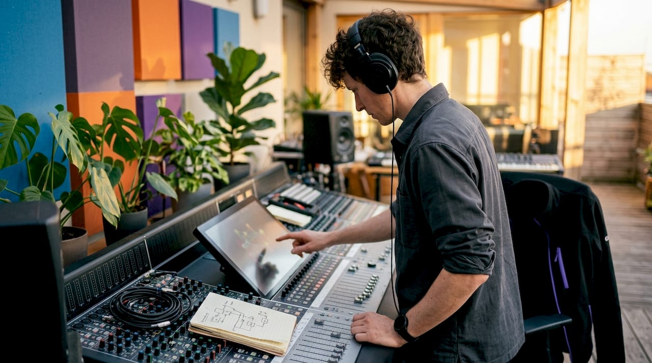
Pro Tip: Map your signal path on paper before building it in code or a DAW. A hand-drawn node diagram catches routing errors, like missing submix nodes or accidental parallel paths, before they become debugging sessions.
A typical studio graph might look like this: two audio file source nodes feed into separate gain nodes for level control, both connect to a submix node, which routes through an EQ processor node, then a limiter processor node, and finally to the output node. Every connection is explicit. Every gain change, format conversion, or remapping is visible in the graph topology. That transparency in routing is a fundamental advantage over legacy fixed-pipeline architectures where signal manipulation happens inside opaque, monolithic code.

Why is determinism critical in audio graph design?
Determinism in audio processing means the graph produces identical output for identical input, every single time, with no variation caused by thread scheduling or memory state. This property is non-negotiable in professional audio. A compressor that behaves differently on two consecutive buffer cycles will introduce audible artifacts, and in live performance contexts, those artifacts are unacceptable.
The DAG structure enforces determinism by requiring strict topological ordering of node execution. Because no cycles exist, the graph manager can compute a fixed processing sequence before the audio thread starts. Every node executes in the same order, every buffer cycle, with no ambiguity about which node runs first.
Real-time safety adds a second constraint on top of determinism. The audio thread must never block. Blocking operations include:
- Memory allocation. Calling malloc or new on the audio thread can trigger the OS memory manager, which may stall for milliseconds.
- Mutex locks. Acquiring a lock that another thread holds causes the audio thread to wait, producing a dropout.
- System calls. File I/O, network access, and similar calls have unpredictable latency and must stay off the hot path.
The solution is a three-phase pipeline: graph building, plan compilation, and runtime execution. Graph building happens on the control thread where memory allocation is safe. Plan compilation converts the graph topology into a flat, ordered execution list. Runtime execution then runs that pre-compiled list on the audio thread with zero allocation and zero locking.
Pro Tip: Pre-allocate all buffers and processing objects during graph compilation. If your audio thread ever calls new or malloc, you have a latency time bomb waiting to fire under load.
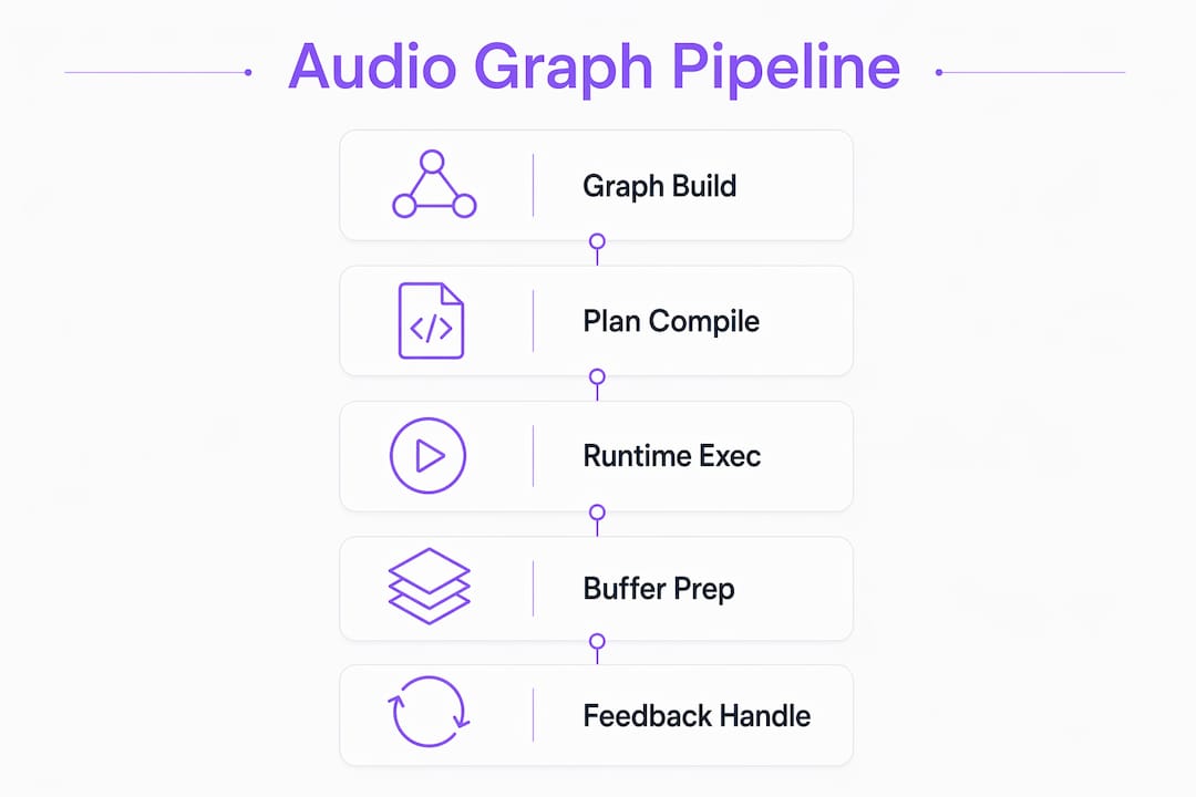
Feedback loops require special handling. When a design genuinely needs a feedback path, such as a physical modeling algorithm that feeds output back into input, a dedicated delay node breaks the cycle. The delay node introduces exactly one buffer of latency, preserving the acyclic structure while allowing the feedback behavior. This is a well-established technique in real-time audio thread programming and applies equally to plugin design and game audio engines.
How do visual graph editors use node-based systems?
Visual graph editors translate the abstract DAG model into a drag-and-drop interface where you connect nodes by drawing lines between ports. Game audio engines and some DAW environments use this approach to let sound designers build complex audio logic without writing code. The node-based DAG structure is identical under the hood; the editor simply provides a graphical front end for the same topology.
Node types in visual editors extend beyond basic sources and processors:
- Container nodes group related audio events and manage playback state as a unit.
- Sequencer nodes trigger audio clips in a defined order, useful for layered sound design.
- Randomizer nodes select from a pool of audio variants at runtime, adding natural variation to repeated sounds like footsteps or impacts.
- Output nodes route the final mix to a bus, a speaker, or a spatial audio renderer.
Visual editors also provide asynchronous preview and error detection during design time. A well-built editor flags configuration problems like duplicate node names, missing connections, or incompatible sample rates before the graph ever runs. That immediate feedback loop accelerates iteration significantly. A sound designer can audition a randomized footstep system in the editor, catch a missing gain node, fix it, and re-test in under a minute.
Runtime execution in these systems works through recursive processing calls. When the audio engine requests a buffer, it calls the output node, which calls its upstream processors, which call their upstream sources, and so on up the graph. The recursion terminates at source nodes that generate or stream raw audio data. This pull-based model maps cleanly onto the DAG structure and keeps execution order consistent with the compiled plan.
For teams working across both visual editors and code-level plugin development, the Kudoflix audio commentary documentation offers practical reference on configuring audio graph topologies in production workflows.
What are the performance trade-offs in complex audio graphs?
Graph traversal overhead is the primary performance cost in complex audio processing architectures. Every node-to-node connection involves a function call, a pointer lookup, and often a virtual dispatch. In a graph with dozens of nodes processing at 48 kHz with a 64-sample buffer, those costs accumulate fast. The dynamic dispatch cost of fine-grained graphs is a known bottleneck, and ultra-low latency applications address it directly.
| Design approach | Flexibility | Runtime overhead | Best use case |
|---|---|---|---|
| Fine-grained node graph | High | High | Prototyping, visual editors |
| Flattened kernel chains | Low | Very low | Ultra-low latency production |
| Hybrid (compile-time flatten) | Medium | Low | Professional plugin frameworks |
| Large processing blocks | Medium | Medium | Streaming and game audio |
Node flattening is the standard solution for latency-critical paths. The compiler analyzes a chain of simple nodes, such as a gain node followed by a filter followed by another gain node, and merges them into a single optimized kernel. That kernel processes the entire chain in one pass with no intermediate function calls. The flattening technique eliminates dynamic dispatch entirely for the merged chain, which is why professional plugin frameworks use it for their core DSP paths.
Runtime graph modification introduces a separate class of problems. Swapping a plugin during playback, rerouting a bus, or changing a parameter that affects graph topology all require communicating changes from the control thread to the audio thread. Pre-allocated memory pools and lock-free queues are the standard mechanism. The control thread writes a change message into a lock-free queue. The audio thread reads it at the start of the next buffer cycle and applies the change atomically. No locks, no allocations, no glitches.
Pro Tip: Design your graph with modification in mind from the start. Retrofitting lock-free communication into a graph that was built assuming static topology is far harder than building it in from day one.
The tension between flexibility and overhead is real and context-dependent. A visual editor for game audio can afford more traversal cost because it runs at lower buffer rates and has more CPU headroom. A VST3 plugin running at 32-sample buffers in a professional DAW cannot. Knowing which regime you are in determines whether you optimize for composability or raw throughput.
Key Takeaways
Audio graph architecture is the definitive model for professional digital audio processing because its DAG structure, deterministic execution, and real-time safety constraints together produce reliable, flexible, and auditable signal chains.
| Point | Details |
|---|---|
| DAG structure prevents feedback | Acyclic graphs enforce a fixed execution order, eliminating unpredictable signal loops. |
| Three-phase pipeline ensures safety | Build, compile, and execute phases keep memory allocation off the real-time audio thread. |
| Node flattening cuts latency | Merging node chains into single kernels removes dynamic dispatch overhead on critical paths. |
| Lock-free queues enable live edits | Pre-allocated pools and lock-free messaging let you modify graphs during playback without glitches. |
| Visual editors share the same model | Node-based DAW and game audio editors use identical DAG topology with a graphical front end. |
Why graph architecture changed how I think about audio systems
The first time I worked on a project that used a proper DAG-based audio engine, the thing that struck me was not the performance. It was the clarity. Every gain change was a node. Every format conversion was visible. I could look at the graph and immediately see where a signal was being attenuated, where it was being split, and where it was being recombined. Legacy fixed pipelines hide all of that inside function call stacks that take hours to trace.
The modularity benefit compounds over time. When you add a new effect to a fixed pipeline, you are editing existing code and hoping nothing breaks. When you add a node to a graph, you are connecting a new unit to existing ports. The rest of the graph does not care. That composability is what makes graph-based systems worth the upfront design investment.
The area where I see producers and engineers get into trouble most often is runtime modification. They build a graph that works perfectly in static configuration, then try to add dynamic rerouting later and hit glitches immediately. The fix is always the same: lock-free queues and pre-allocation, designed in from the start. If you are building anything that needs live parameter changes or plugin swapping, read the audio signal flow fundamentals before you write a single line of audio thread code.
My honest prediction for where this goes next: dynamic graph modification will become a first-class feature in professional plugin formats, not an afterthought. The frameworks that nail lock-free graph editing at 32-sample buffers will define the next generation of professional audio tools.
— Kai
Vector-dsp and professional audio graph development
Vector-dsp builds professional audio tools on the same DAG-based architecture principles described throughout this article. Every plugin in the Vector-dsp lineup targets VST3, AU, and AAX formats with real-time safety and deterministic execution as non-negotiable design requirements, not optional features.
If you are a music producer or sound engineer who wants tools built on these principles, Vector-dsp's approach to modular audio processing reflects the architecture model this article covers: explicit signal routing, pre-compiled execution plans, and lock-free runtime behavior. The goal is audio software that behaves predictably at any buffer size, in any session complexity.
FAQ
What is audio graph architecture in simple terms?
Audio graph architecture is a system where audio processing units connect as nodes in a directed acyclic graph, with audio data flowing along edges from sources through processors to outputs. The DAG structure enforces a fixed, deterministic execution order for every buffer cycle.
How does an audio graph differ from a fixed pipeline?
A fixed pipeline processes audio through a hardcoded sequence of steps with no visibility into routing. An audio graph makes every connection explicit, so engineers can see and modify signal routing, gain changes, and format conversions directly in the graph topology.
Why must audio graphs avoid cycles?
Cycles create feedback loops that make execution order ambiguous and can cause deadlocks on the real-time audio thread. When a feedback path is genuinely needed, a dedicated delay node breaks the cycle while preserving the acyclic structure.
What is the role of the AudioContext in the Web Audio API?
The AudioContext is the master clock and scheduling layer for the entire node graph. It manages sample rate, timing, and the connection topology of all audio nodes, ensuring synchronized playback across the graph.
How do you modify an audio graph during playback without glitches?
Safe runtime modification requires pre-allocated memory pools and lock-free queues that pass change messages from the control thread to the audio thread. This approach avoids memory allocation and mutex locking on the hot audio path, preventing dropouts during live edits.