Loudspeaker DSP Processing Examples for Audio Pros
Loudspeaker DSP Processing Examples for Audio Pros
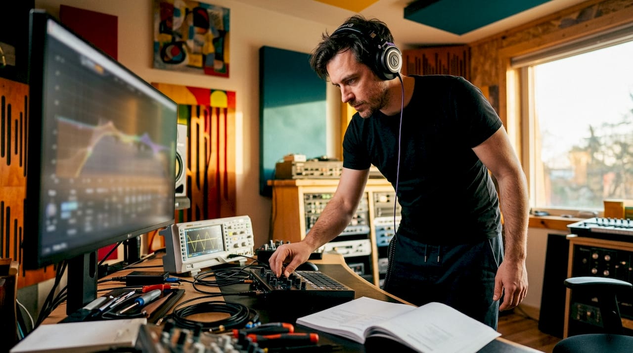
Loudspeaker DSP processing is defined as the mathematical manipulation of audio signals to correct frequency response, manage dynamics, route crossover bands, and align driver timing in real time. Unlike amplification, which only adjusts signal level, DSP mathematically corrects acoustic environment and driver limitations to produce better sound reproduction. These loudspeaker dsp processing examples cover the full range of techniques audio professionals use daily, from parametric EQ and FIR filter design to spatial audio and driver protection. Understanding the core DSP algorithm types behind each technique is what separates a tuned system from a merely loud one.
1. Loudspeaker DSP processing examples: frequency response shaping with parametric EQ
Parametric EQ is the most direct DSP tool for correcting driver anomalies and room-induced coloration. A woofer with a 6 dB peak at 80 Hz, caused by a nearby boundary wall, gets a narrow notch filter applied at exactly that frequency. The result is a flat, accurate low end without touching the rest of the spectrum. Professional loudspeaker DSP covers this as one of four fundamental tasks alongside dynamic control, crossover filtering, and time alignment.
The key advantage of parametric EQ over graphic EQ is surgical control over center frequency, bandwidth (Q), and gain independently. A high-Q filter at 2.5 kHz can remove a harsh cone resonance without affecting the surrounding octave. Audio engineers tuning studio monitors or PA systems rely on this precision to match a target curve measured with a calibrated microphone.
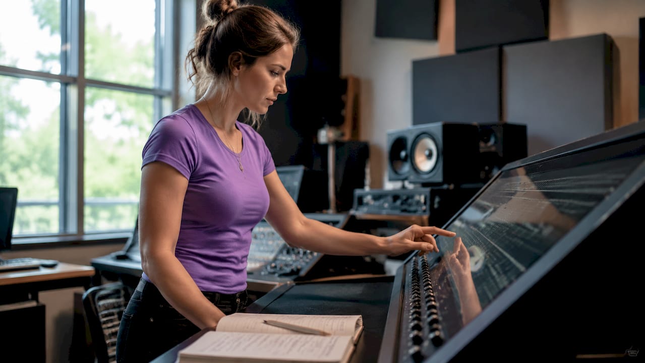
Pro Tip: Use a measurement tool like Room EQ Wizard alongside your DSP platform to capture the actual frequency response before applying any filters. Correcting what you measure beats correcting what you hear.
2. Dynamic range control: compression and limiting for driver protection
DSP protects loudspeakers with output limiting and compression to prevent driver damage and distortion. A limiter set 3 dB below the tweeter's thermal limit catches transient peaks before they cause voice coil damage. Compression applied to the woofer band during high-SPL passages keeps excursion within safe limits without audible pumping.
This is not just a safety feature. Dynamic control shapes the perceived loudness and punch of a system. A well-configured multiband compressor in a live PA DSP processor keeps the kick drum present and controlled even as the mix gets louder. The difference between a system that sounds tight at 110 dB and one that sounds strained is almost always in the dynamic processing chain.
3. Crossover filtering: routing frequencies to the right driver
Digital crossover filters replace passive LC networks with precise, adjustable IIR or FIR filters that route frequency bands to the correct driver. A 3-way system routes everything below 250 Hz to the woofer, 250 Hz to 3 kHz to the midrange, and above 3 kHz to the tweeter. DSP crossovers allow slope steepness, crossover frequency, and filter type to be changed in software without rewiring.
Linkwitz-Riley filters at 24 dB per octave are the standard choice for most professional systems because they sum flat at the crossover point. Bessel filters offer better transient response at the cost of a shallower rolloff. The ability to A/B these choices in real time, without soldering, is one of the clearest advantages of digital crossover design over passive networks.
4. Time alignment: synchronizing drivers for phase coherence
Time alignment uses DSP delay to synchronize the acoustic output of drivers that are physically offset from each other. A tweeter mounted 15 mm behind the woofer baffle arrives at the listener's ear slightly later. A delay of roughly 0.04 ms applied to the woofer output corrects this offset and restores phase coherence at the crossover frequency.
The audible result is a sharper stereo image and a more coherent center image. Without time alignment, the crossover region sounds smeared because two drivers are reproducing the same frequencies out of phase. Delay speaker applications in large venues use the same principle to align delay towers with the main system. A 5-way DIY loudspeaker system can be fully tuned for time alignment, EQ, and crossover in under a day using specialized DSP software.
5. FIR vs. IIR filter selection: the trade-off every engineer faces
FIR filters deliver linear phase response, meaning all frequencies are delayed by the same amount. IIR filters are computationally cheaper and add less latency but introduce phase distortion that varies with frequency. The choice between them defines the character of a DSP system. Professionals choose FIR when phase accuracy is critical and IIR when low latency and efficiency are the priority.
A 600-tap FIR filter at 48 kHz adds 6 ms of group delay. That is acceptable in a studio monitor or a fixed installation but problematic in a live monitor wedge where the performer hears an echo. Minimum-phase conversion of a linear-phase FIR filter halves the latency with some phase distortion in the passband. The trade-off is real, and the right answer depends on the application.
Pro Tip: For live monitoring, use minimum-phase IIR filters to keep latency below 3 ms. For studio playback and mastering speakers, linear-phase FIR filters give you the most accurate imaging.
6. Least-Squares FIR filters: removing narrow-band interference
Least-Squares FIR filter design targets specific interference frequencies with high attenuation and minimal impact on the surrounding spectrum. A filter of order 200 achieves 100.65 dB of stopband attenuation and only 0.44 dB of passband ripple when removing a narrow-band 15.2 kHz interference tone. That level of attenuation is effectively inaudible suppression of the interference while leaving the rest of the audio intact.
This technique is used in professional loudspeaker systems to remove RF interference picked up by long cable runs, suppress switching noise from Class D amplifiers, and eliminate narrow resonances in horn-loaded compression drivers. The design requires careful specification of the passband and stopband edges, but the result is a filter that outperforms windowed FIR methods for this specific task.
7. Adaptive FIR filtering: noise cancellation in headphones and monitors
Adaptive FIR filters update their coefficients in real time based on a reference signal, making them the core technology in active noise cancellation. Consumer noise-canceling headphones use adaptive FIR filters with 128–512 taps at 48–96 kHz to achieve 20–30 dB of attenuation below 1 kHz with latency under 3 ms. That combination of attenuation depth and speed is what makes modern ANC headphones effective against low-frequency cabin noise on aircraft.
The same principle applies to studio reference monitors in acoustically compromised rooms. An adaptive filter can track slow changes in the acoustic environment, such as a door opening or HVAC noise, and adjust its correction in real time. This is a more advanced application than static EQ and requires a reference microphone and a DSP platform capable of running adaptive algorithms.
8. Polyphase decomposition: efficient filtering on embedded hardware
Polyphase decomposition splits a high-order FIR filter into M parallel sub-filters, cutting computational cost by a factor of M. This makes it possible to run complex filters on low-power DSP chips embedded in amplifier modules and active loudspeaker PCBs. Without polyphase decomposition, a 512-tap filter at 96 kHz would exceed the processing budget of most embedded processors.
The practical result is that manufacturers can embed sophisticated crossover and EQ processing directly on the amplifier board without adding a dedicated DSP chip. This reduces cost, board space, and latency. Audio engineers designing active loudspeakers for portable or battery-powered applications rely on polyphase techniques to fit professional-grade filtering into constrained hardware.
9. Anti-aliasing filters: protecting signal integrity at the ADC stage
Anti-aliasing filters placed before the analog-to-digital converter prevent input frequencies above half the sampling rate from folding back into the audio band as distortion. At a 48 kHz sample rate, any signal above 24 kHz must be attenuated before conversion. Without this filter, a 30 kHz tone aliases to 18 kHz and appears as an audible artifact in the processed signal.
This is one of the most common DSP failures in poorly designed audio hardware. The fix is a steep low-pass filter with a cutoff just below the Nyquist frequency. Modern sigma-delta ADCs include oversampling and digital decimation filters that handle most of this automatically, but engineers designing custom DSP hardware still need to verify the anti-aliasing performance with a spectrum analyzer.
10. Spatial audio and HRTF convolution: immersive loudspeaker processing
DSP enables spatial audio by convolving the signal with Head-Related Transfer Functions (HRTFs), which simulate how sound reaches the ears from different directions. Dolby Atmos and DTS:X both rely on DSP rendering engines that apply per-object HRTF convolution in real time to create height and surround perception from a limited number of physical loudspeakers. The DSP algorithm design behind these formats is among the most computationally demanding in consumer audio.
For loudspeaker system designers, HRTF convolution is also used in binaural rendering for headphone monitoring of spatial mixes. A stereo pair of studio monitors can simulate a 7.1.4 Atmos bed using crosstalk cancellation DSP, which subtracts the signal reaching the wrong ear. This technique requires precise speaker placement and room treatment but delivers a convincing spatial image for mix checking.
11. Hardware vs. software DSP: choosing the right platform
Hardware and software DSP processing each have distinct advantages depending on the application context. Hardware DSP processors like those embedded in active loudspeaker amplifier boards offer fixed latency, standalone operation, and no dependency on a host computer. Software DSP running as VST3, AU, or AAX plugins offers unlimited flexibility, easy updates, and integration with a DAW workflow.
| Platform | Latency | Flexibility | Best Use Case |
|---|---|---|---|
| Embedded hardware DSP | Very low (under 1 ms) | Fixed at manufacture | Active loudspeakers, live PA |
| Standalone DSP processor | Low (1–5 ms) | Configurable via software | Installation audio, touring |
| Software plugin (VST3/AU/AAX) | DAW-dependent | Fully programmable | Studio mixing, plugin design |
| FPGA-based DSP | Extremely low | High but complex | Research, custom hardware |
The selection criteria for audio professionals come down to three factors: latency requirements, the need for field reconfiguration, and integration with existing signal chains. A touring engineer needs a hardware processor that survives road conditions and boots in seconds. A studio engineer building a custom monitor controller benefits from software DSP that can be updated as the design evolves.
Key takeaways
Loudspeaker DSP processing works because it combines frequency shaping, dynamic control, crossover routing, and time alignment into a single programmable signal chain that hardware alone cannot replicate.
| Point | Details |
|---|---|
| FIR vs. IIR filter choice | Use FIR for phase accuracy in studio monitors; use IIR for low-latency live monitoring. |
| Anti-aliasing is non-negotiable | Place a steep low-pass filter before the ADC to prevent aliasing distortion in any DSP system. |
| Time alignment improves imaging | Apply per-driver delay to synchronize acoustic output and restore phase coherence at crossover. |
| Polyphase decomposition saves resources | Split high-order FIR filters into sub-filters to run complex processing on embedded hardware. |
| Dynamic protection extends driver life | Combine output limiting and compression to prevent thermal and excursion damage at high SPL. |
Why I think most engineers underuse DSP before they even start tuning
Most audio engineers reach for EQ first. That instinct is understandable, but it skips the step that makes EQ work correctly. Before applying any filter, you need to understand the acoustic environment and the driver's behavior in that environment. A parametric boost at 100 Hz sounds different in a reflective concrete room than in a treated studio. DSP cannot fix a bad room. It can only correct what the measurement shows.
The filter selection decision is where I see the most costly mistakes. Engineers apply linear-phase FIR filters to live monitor wedges because they read that FIR is "better." The 6 ms latency that results makes the performer feel like they are singing into a delay unit. IIR filters with minimum-phase behavior are the right tool for that job. The future of DSP technology points toward adaptive systems that select filter types automatically based on context, but we are not there yet in most production environments.
The other pitfall I see consistently is incorrect gain staging before the DSP stage. A signal clipping at the ADC input produces harmonics that no amount of downstream filtering will remove. Anti-aliasing and proper input gain are the foundation. Everything else builds on top of that. Iterative measurement and refinement, using real-time filter error displays where the software shows you the difference between target and actual response, is the only reliable path to a well-tuned system. Guessing and listening is slower and less accurate than measuring, adjusting, and measuring again.
— Kai
Vector-dsp resources for professional loudspeaker processing
Audio professionals who want to go deeper on any of these techniques will find Vector-dsp's library of DSP design guides and blog articles built specifically for this level of work.
Vector-dsp covers everything from foundational DSP signal processing concepts to advanced algorithm design for loudspeaker and plugin applications. The site is built for engineers who already know the basics and need precise, technically grounded resources to push their systems further. Visit Vector-dsp to access the full catalog of tools, tutorials, and design references for professional audio DSP work.
FAQ
What are the core loudspeaker DSP processing tasks?
The four core tasks are frequency response shaping, dynamic range control, crossover filtering, and time alignment. A 5-way loudspeaker system can be fully tuned across all four areas in under a day using specialized DSP software.
When should I use FIR filters instead of IIR filters in a loudspeaker system?
Use FIR filters when phase accuracy is the priority, such as in studio monitors or mastering systems. Use IIR filters when latency must stay below 3 ms, as in live monitor wedges or real-time PA systems.
What causes aliasing in loudspeaker DSP systems?
Aliasing occurs when input frequencies above half the sampling rate enter the ADC without filtering. A steep low-pass anti-aliasing filter placed before the ADC stage prevents this distortion from appearing in the processed audio.
How does polyphase decomposition help embedded loudspeaker DSP?
Polyphase decomposition splits a high-order FIR filter into parallel sub-filters, reducing the computational load by a factor equal to the number of sub-filters. This makes complex filtering practical on low-power DSP chips embedded in active loudspeaker amplifier boards.
What DSP techniques protect loudspeaker drivers from damage?
Output limiting, dynamic compression, and crossover routing work together to prevent driver damage. Limiting catches transient peaks before they exceed thermal limits, while crossover routing prevents low-frequency energy from reaching tweeters not designed to handle it.