Linear Phase Crossovers for Engineers: Plan for 40 ms Latency
Linear Phase Crossovers for Engineers: Plan for 40 ms Latency
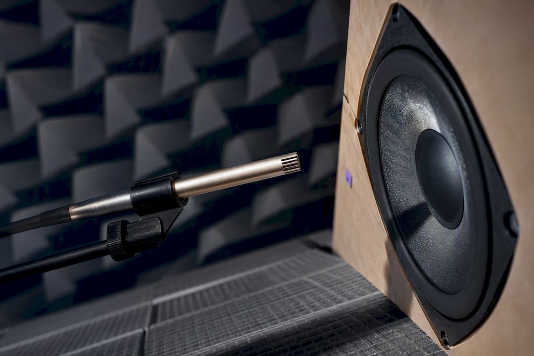
A linear-phase crossover splits an audio signal into bands using filters that all share the same, frequency-independent time delay, so the summed output is just a delayed copy of the original waveform. That preserves transient alignment across drivers and can sharpen imaging, but it costs latency and CPU cycles that minimum-phase designs avoid. Pick it for studio monitoring, mastering, and multi-way loudspeaker systems where phase accuracy outweighs the delay penalty. Skip it for live sound or anything monitored in real time through a microphone.
TL;DR:
- Linear-phase crossovers require long filters, resulting in increased latency, which makes them suitable mainly for studio monitoring and mastering, not live sound.
- They provide time-aligned drivers across the entire frequency band, improving imaging and phase coherence, and support better off-axis response in multi-way loudspeakers.
- Longer FIR filters needed for steep slopes and low frequencies can introduce pre-ringing and high CPU load, but hybrid and multirate approaches reduce these issues.
- Designing effective linear-phase crossovers begins with precise in-situ measurements, appropriate filter length based on latency limits, and iterative testing of impulse and square-wave responses.
- Tools like rePhase and convolution engines enable building and deploying linear-phase filters, while practical constraints limit their use to applications where latency is acceptable and phase coherence is critical.
Table of Contents
- What Is a Linear-Phase Crossover, Exactly?
- Why Engineers Choose Linear-Phase Crossovers (and What It Costs)
- FIR, IIR Approximations, and Hybrid Methods
- How to Design a Linear-Phase Crossover, Step by Step
- Real Numbers: Tap Counts and Latency You Can Plan Around
- Tools and References Worth Bookmarking
- Notes From Kai and Vector DSP's Design Bench
- When I Reach for Linear Phase and When I Don't
- Build Your Linear-Phase Chains Without Fighting Your DAW's Latency Budget
- Sources
- FAQ
What Is a Linear-Phase Crossover, Exactly?
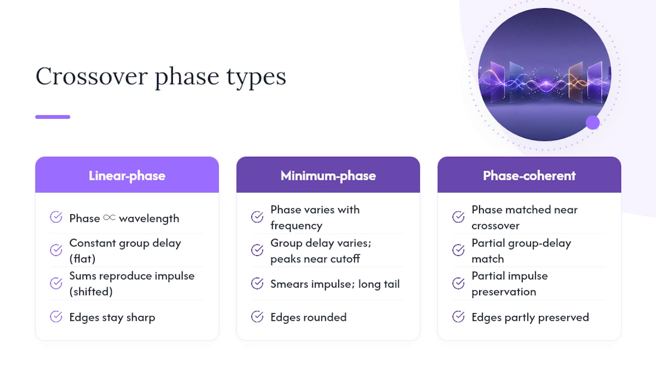
A crossover splits a signal into frequency bands, and "linear phase" describes a specific relationship between phase shift and frequency: the phase delay increases proportionally with wavelength, which means every frequency component gets delayed by the exact same amount of time. That constant number is called group delay, and it's the mathematical signature of a linear-phase filter. Plot phase against frequency and you get a straight line. Plot group delay and you get a flat one.
Minimum-phase filters, the kind found in most analog crossovers and countless digital ones, don't do this. Their phase shift varies with frequency, which means group delay varies too, usually rising near the cutoff before settling. That's not automatically a flaw. Minimum-phase designs are efficient and widely trusted, and Linkwitz-Riley alignments remain the default in commercial loudspeaker DSP for good reason. But they smear time alignment in the crossover region in ways a linear-phase EQ approach is specifically built to avoid.
The practical payoff shows up in the time domain. Feed a linear-phase crossover a perfect impulse, sum the outputs, and you get the same impulse back, shifted in time. Feed it a square wave and the summed edges stay sharp. A minimum-phase crossover, by contrast, will smear that impulse into something with a rounded leading edge and a longer tail, even though the magnitude response measures identically. Phase-coherent designs sit somewhere between the two, matching phase only near the crossover point rather than across the full band, which is a different (and looser) goal than true linear phase.
Why Engineers Choose Linear-Phase Crossovers (and What It Costs)
The biggest draw is time-domain fidelity. When every band exits the crossover with identical delay, transients from different drivers arrive at the listening position in sync, which tightens imaging and depth on well-recorded material. Loudspeaker systems built around linear-phase crossover filters keep drivers phase-aligned at every frequency, not just at the crossover point, which Linea Research's engineering documentation notes greatly simplifies integrating multi-way systems, since a single fixed delay can bring two dissimilar boxes into alignment instead of chasing phase errors band by band.
There's also a directivity benefit that gets less attention than it deserves. In pair-wise symmetric multi-way loudspeakers, research on linear-phase digital crossover filters shows they help maintain constant beamwidth and more uniform off-axis response, which matters enormously for line arrays and any system where polar consistency drives the buying decision.
None of this is free. The tradeoffs cluster into four areas:
- Latency: exact linear phase demands long filters, and long filters take time to compute, adding tens of milliseconds of delay before any signal reaches the output.
- Pre-ringing: the symmetric impulse response that creates linear phase also creates energy before the main transient, audible as a faint smear on sharp percussive material.
- Computation: long FIR filters chew through more CPU and memory than a handful of biquads ever will.
- Polar interaction: getting the summed magnitude response flat while keeping phase linear can fight against directivity goals near the crossover, especially with widely spaced drivers.
Pro Tip: If pre-ringing worries you on a specific program, don't abandon linear phase, just shorten the filter and accept a gentler slope. A 24 dB/octave linear-phase crossover with a modest tap count usually rings less than a brick-wall version, and the difference is rarely audible outside of test tones.
FIR, IIR Approximations, and Hybrid Methods
FIR filters are the only way to get exact linear phase, full stop. A symmetric FIR impulse response guarantees constant group delay by construction, and that's why every serious linear-phase crossover tool builds on FIR at its core. The catch is that sharp cutoffs and steep slopes require long impulse responses, and research on IFIR-based crossover networks confirms this directly: longer taps mean more latency and more multiply-accumulate operations per sample, which strains real-time systems.
IIR-based approximations take the opposite bet. Instead of a true linear-phase filter, they use time-reversed IIR structures or complementary filter pairs that approximate the phase response with far less computation. An AES paper on IIR-based linear-phase crossover design lays out proposals for low-latency, near-linear-phase crossovers built this way. They cut delay and CPU load substantially, but they trade away exact phase linearity. Close to linear, not identical to it.
Hybrid methods split the difference by being selective about where they spend computational budget:
- IFIR (interpolated FIR) upsamples a short filter designed at a lower rate, cutting the number of high-rate taps needed for a narrow transition band.
- Multirate processing runs different bands at different sample rates, matching computational cost to the actual bandwidth each band needs.
- Windowed or apodized FIR trims filter length by accepting a slightly wider transition band in exchange for fewer taps and less delay.
According to the IFIR crossover network research, these multirate strategies retain narrow transition bands and true linear phase while meaningfully reducing the tap count compared to a single-rate FIR design covering the same specification. That's the practical unlock for anyone trying to run linear-phase crossovers on constrained hardware rather than a workstation.
How to Design a Linear-Phase Crossover, Step by Step
Good crossover design starts with measurement, not filter math. Skipping straight to a target curve is the single most common way projects go wrong.
- Measure each driver in situ. Capture magnitude, phase, group delay, and polar response (at least 0°, 15°, 30°, and 45° off axis) for every driver in its actual enclosure and position. Phase-coherent design work consistently finds that real driver behavior, not filter theory, dominates the final result, so this step isn't optional.
- Choose crossover frequency and slope from the measured data, not from a spec sheet. Pick a point where both drivers have flat, well-behaved response and adequate power handling, with enough separation from resonances and breakup modes.
- Set a latency budget before designing the filter. Sound reinforcement work usually caps acceptable added delay well under 10 milliseconds; studio monitoring and mastering can tolerate 20 to 50 milliseconds without anyone noticing. Group delay in a linear-phase FIR scales directly with tap count and sample rate, so this budget determines how many taps you can afford.
- Design the linear-phase FIR filters to the target slope and frequency, then check the summed magnitude response for ripple or dips at the crossover point.
- Equalize to flatten what the crossover alone can't fix. Driver anomalies, diffraction, and cabinet resonances all show up in the summed response. Practitioners routinely pair FIR crossovers with targeted EQ correction rather than expecting the filter to do everything, an approach covered in more depth in these multiband processing fundamentals.
- Verify with a step response and square-wave test. A well-executed linear-phase crossover should show a clean, symmetric step and preserved square-wave edges through the crossover region.
- Confirm with listening tests, ideally comparing switchable linear-phase and minimum-phase versions on transient-heavy material like plucked strings or drum hits.
Pro Tip: Run the step-response check before you trust your ears. Pre-ringing is easy to miss on program material but obvious on a step, and catching it there saves a wasted listening session later.
Real Numbers: Tap Counts and Latency You Can Plan Around
Here's where theory turns into a spreadsheet. Crossover placement, sample rate, and slope steepness all interact to determine how many taps you need and how much delay you're signing up for.
Low-frequency crossovers are the expensive ones. Getting a sharp transition at 80 to 120 Hz demands a long filter relative to the wavelengths involved, which is why full-range linear-phase systems often carry 40 milliseconds or more of latency concentrated almost entirely in the low band. Doubling the sample rate roughly doubles the tap count needed for the same time-domain filter length, since more samples pass per second, though the latency in milliseconds stays about the same.
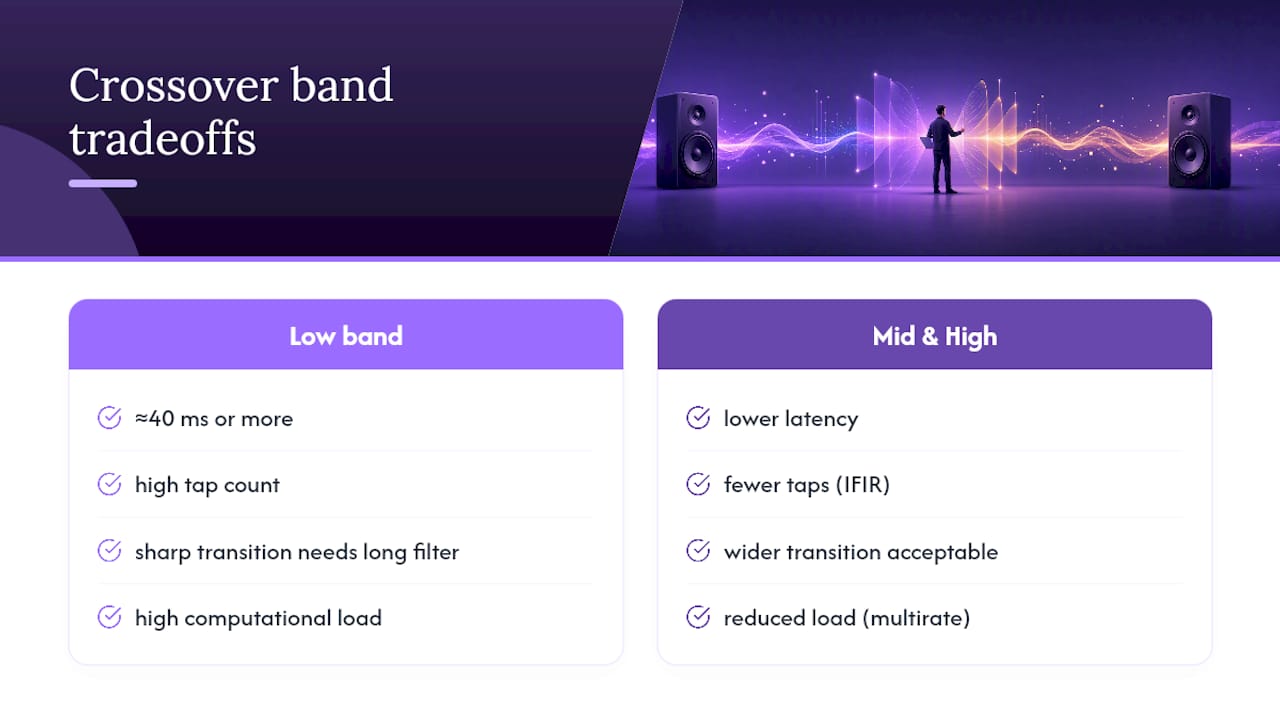
Mid and high crossovers are far cheaper because the wavelengths are shorter and the transition band can occupy proportionally more of the spectrum without sounding compromised. This is where IFIR and multirate techniques earn their keep, concentrating filter taps at a lower internal processing rate and cutting both computational load and pre-ringing risk without giving up linear phase. The tradeoff you're managing here is direct: fewer taps means less pre-ringing and less latency, but also a wider, less surgical transition band. For most program material, that trade favors shorter filters more often than engineers assume.
Tools and References Worth Bookmarking
rePhase is the tool most practitioners reach for first. It's a free FIR generator built specifically for linear-phase active crossover design, and it lets you sculpt magnitude and phase targets, then export convolution-ready impulse responses for whatever platform you're deploying to. The workflow is graphical and iterative: set targets, generate, measure the result, adjust, repeat.
Once you've got an impulse response, you need somewhere to run it. That means a convolution plugin in your DAW, a hardware DSP processor with convolution support, or a loudspeaker management platform that accepts custom FIR coefficients. Latency budgeting matters here just as much as it did at design time, since the convolution engine itself adds a frame or two of buffering on top of the filter's own delay.
For deeper background, three sources cover the field well:
- D.B. Keele Jr.'s work on pair-wise symmetric multi-way loudspeakers for the directivity angle.
- The AES paper on IIR-based linear-phase design for anyone chasing lower latency.
Notes From Kai and Vector DSP's Design Bench
Kai leads the DSP thinking behind Vector DSP's plugin work, where real-time constraints make every millisecond of latency a design decision, not an afterthought. The recurring lesson from building phase-shift-aware crossover tools: the filter is rarely the hard part. Compensating for actual driver behavior and validating alignment against real-world DSP deployments takes far longer than generating the impulse response itself. Vector DSP's low-latency focus grew directly out of watching linear-phase designs stall in real-time contexts where every extra tap has a cost.
When I Reach for Linear Phase and When I Don't
Linear phase earns its cost in mastering, studio monitoring, and multi-way systems where imaging and integration matter more than milliseconds. For live sound, broadcast, or anything monitored through a mic in the room, minimum-phase or Linkwitz-Riley crossovers usually win on latency alone. My advice to stakeholders is blunt: name the latency number before anyone hears the phase benefit, because that tradeoff is the whole decision.
— Kai
Build Your Linear-Phase Chains Without Fighting Your DAW's Latency Budget
Plugin architecture can be designed around the constraint that linear-phase processing is only usable when the latency cost is predictable and manageable in real time. A multi-lane parallel effects architecture, with per-lane EQ targeting, can provide the surgical band control a crossover workflow demands, without forcing a guessing game about what a DAW's buffer can absorb.
If you've been designing crossover chains by stacking generic EQ and convolution plugins, a purpose-built tool changes the math. ToneLab runs as VST3, AU, or AAX on Windows and macOS, with low-latency real-time DSP built for exactly this kind of band-splitting and phase-sensitive work. Pair it with the parallel transient-shaping techniques covered elsewhere on our site, and you get a practical path from measurement to a finished, phase-aware mix chain. Try the ToneLab demo and see how it handles your own crossover point before committing to a full license.
Sources
Start with the Linea Research LIR white paper for the systems-integration argument and supporting plots. D.B. Keele Jr.'s article on pair-wise symmetric loudspeakers remains the clearest technical treatment of the directivity benefit. For implementation tradeoffs, read the AES paper on IIR-based linear-phase design and the IFIR-based crossover network paper. Generate your own filters with rePhase, and cross-check crossover slope theory against Rane's archived Bessel filter note.
- LIR Linear Phase Crossovers — Linea Research (white paper)
- Application of linear-phase digital crossover filters to pair-wise symmetric multi-way loudspeakers — D.B. Keele Jr.
- rePhase — FIR generation tool
FAQ
Does a crossover improve sound quality?
A crossover doesn't inherently improve sound quality; it protects drivers and divides frequency responsibility correctly. A well-designed linear-phase crossover can improve perceived imaging and transient clarity by keeping bands time-aligned, but a poorly designed one can just as easily introduce audible smearing or dips.
When should you use linear phase on EQ?
Use linear-phase EQ when you're correcting tonal balance late in a mastering or mix chain and need to avoid the phase shift that minimum-phase EQ introduces near boosted or cut frequencies. It's less useful in tracking or live contexts, where its added latency becomes a real problem rather than a rounding error.
What is the best crossover setting for speakers?
There's no universal setting; it depends on driver size, enclosure, and the specific pair being integrated. Measured data, not a spec-sheet number, should drive the final crossover point and slope choice.
Why is 80 Hz often used as a subwoofer crossover point?
An 80 Hz crossover is a common practice for sub-to-satellite integration because it reduces the risk of localizing the subwoofer while keeping excursion demands on the satellite speakers manageable, a balance documented in passive crossover design notes. It's a solid starting point, not a fixed rule; smaller satellites or larger subs can shift the ideal point higher or lower.