Frequency Crossover Without Phase Shift: What's Actually Possible
Frequency Crossover Without Phase Shift: What's Actually Possible
You cannot build a practical multi-way crossover that produces zero phase shift at every frequency. That's not a limitation of cheap parts or lazy engineering. It's a consequence of how filters work. What you can build is a crossover that's phase-coherent at the crossover frequency, or a digital filter that holds linear phase across the entire band at the cost of latency.
Here's the vocabulary you need before going further. Phase shift is the time offset a filter introduces between input and output, expressed in degrees relative to frequency. Group delay is the practical, frequency-dependent version of that same idea, measured in milliseconds, and it's what your ears actually respond to. Phase-coherent means two drivers' outputs line up at one specific point, usually the crossover frequency. Linear-phase means the delay is flat across the whole spectrum, not just at one point. Minimum-phase describes standard analog and IIR filters, where phase shift increases with filter order but stays tied to the magnitude response in a predictable way.
So what should you actually do?
- Need low latency and moderate slopes? A Linkwitz–Riley LR-2 or LR-4 alignment gets you phase coherence at the crossover point with almost no processing delay.
- Need flat group delay across the whole band, and latency isn't a problem? Go linear-phase with an FIR filter, or a lower-latency variant like Linea Research's LIR.
- Working in a niche low-latency hardware context where DSP isn't an option at all? Analog topologies like the Resonant Transformer Router concept are worth studying, with real caveats about component tolerances.
Key Takeaways
Absolute zero phase shift across the full audio band isn't achievable in a practical crossover, but phase coherence at the crossover point or full linear-phase behavior across the band both are, depending on your latency budget.
| Point | Details |
|---|---|
| Zero phase shift is unrealistic | Aim for phase coherence at the crossover point or linear-phase across the band, not absolute zero shift everywhere. |
| LR-2 is the low-latency default | Linkwitz–Riley LR-2 or LR-4 gives in-phase driver outputs at the crossover frequency with minimal processing delay. |
| Linear-phase costs latency | FIR and LIR filters flatten group delay across the band but require longer kernels and added delay. |
| Acoustic alignment beats filter choice | Per-driver delay compensation for acoustic center offsets often matters more than which crossover topology you pick. |
| Vector-dsp maps directly to this workflow | Per-lane delay, EQ targeting, and low-latency VST3/AU/AAX processing support the exact correction steps this guide recommends. |
Table of Contents
- Why Phase Shift At The Crossover Point Actually Matters
- How The Common Crossover Topologies Actually Behave In Phase
- Linear-Phase Vs Minimum-Phase: What FIR And LIR Actually Cost You
- Advanced Approaches: All-Pass Compensation And Analog Alternatives
- A Practical Design Checklist For Minimizing Audible Phase Issues
- How To Measure And Verify Phase Alignment After The Fact
- The People And Products Behind This Guide
- What Actually Deserves Your Attention Here
- Get The DSP Precision This Guide Recommends
- Sources
Why Phase Shift At The Crossover Point Actually Matters
Phase shift isn't an abstract spec sheet number. It changes what you hear.
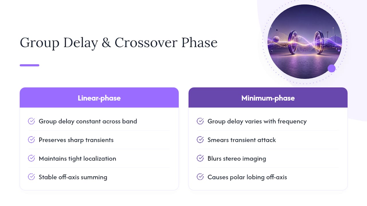
When a filter shifts phase, it delays some frequencies relative to others. That reshapes the waveform. Nelson Pass, in his frequently cited analysis of phase-coherent crossover networks, uses square waves to make this visible: run one through a crossover with mismatched phase, and the sharp transient edges smear into something rounder and softer. A snare hit or a plucked string loses the crispness of its attack. You're not imagining it when a mix feels "smeared" through one system and "tight" through another. Often it's phase behavior at the crossover, not the tweeter or the amp.
Localization takes a similar hit. Stereo imaging depends on your brain comparing timing and level differences between your ears down to fractions of a millisecond. When a crossover introduces frequency-dependent phase shift, it distorts those timing cues asymmetrically across the band. Instruments that should sit in a tight, specific spot in the stereo field instead smear across a wider, vaguer area. This is why some multi-way speakers image beautifully while others, with seemingly similar drivers and specs, sound diffuse.
There's also a spatial dimension most crossover discussions skip: off-axis behavior. When the low-pass and high-pass sections of a crossover have different phase responses relative to each other, the summed output changes depending on listening angle. On-axis you might get a flat response; ten degrees off-axis, a null or a bump appears where the two driver outputs no longer sum cleanly. This is called polar lobing, and it's a direct product of phase mismatch, not just driver spacing.
Group delay is the number that ties all of this together. It's the derivative of phase versus frequency, and it tells you, in milliseconds, how much a specific frequency is delayed relative to the rest. A crossover with wildly varying group delay across its passband is a crossover that will smear transients and blur imaging, even if its magnitude response measures dead flat. Linear-phase design, by definition, holds group delay constant. That's the entire point of choosing it.
Pro Tip: Don't judge a crossover by its magnitude response alone. Two crossovers can measure identically flat on a frequency response sweep and sound completely different because their phase and group delay behavior diverge.
A crossover claiming a 0-degree phase difference at the crossover point, as Linkwitz–Riley 24 dB/octave designs do at their summed -6 dB point, only delivers that benefit if the physical drivers are acoustically aligned too. Electrical phase coherence and acoustic phase coherence are two different problems, and fixing one doesn't automatically fix the other.
How The Common Crossover Topologies Actually Behave In Phase
Pick a topology, and you're picking a phase behavior whether you think about it or not. Here's what each one actually does, not just what its slope spec suggests.
- First-order (6 dB/octave) crossovers. These introduce a 90-degree phase shift at the crossover frequency between the low-pass and high-pass sections, but the outputs sum to a perfectly flat magnitude and phase response when you add them back together. That's the appeal: mathematically, a first-order crossover reconstructs the original signal with no ripple. In practice, the shallow slope means significant overlap between drivers, which limits its use to full-range planar or ribbon designs and a handful of high-end passive speakers where driver overlap isn't a liability.
- Butterworth crossovers (2nd, 3rd, 4th order, and beyond). Butterworth alignments optimize for maximally flat magnitude response within each filter section, but they don't sum flat the way first-order does. Cascade two identical Butterworth filters of the same order and you get steeper rolloff, but the summed output at the crossover point develops a phase discrepancy that grows with filter order. This is exactly the problem that led to the next topology on this list.
- Linkwitz–Riley crossovers (LR-2, LR-4, LR-8). These are built by cascading two Butterworth filters of half the target order, which is a deliberate trick to fix the summing problem. An LR-4 crossover is two cascaded 2nd-order Butterworth filters, giving a 24 dB/octave slope while keeping the low-pass and high-pass sections exactly in phase with each other at the crossover frequency. That's why LR topologies became the default in professional loudspeaker design.
Here's the rule of thumb that trips up a lot of engineers moving from theory to bench work:
- Even-order LR crossovers (LR-2, LR-4, LR-8) produce outputs that are in-phase with each other at the crossover frequency, and the summed output is also in-phase with the original input signal.
- Odd-order LR crossovers produce outputs that are in-phase with each other at the crossover frequency, but the summed output ends up 180 degrees out of phase with the input, requiring a polarity flip on one driver to correct it, which then reintroduces a different phase problem off-axis.
- LR-2 specifically gives you a phase-coherent output between drivers at the crossover frequency with minimal processing overhead, which is why it's the default starting point for live sound and near-field monitor crossovers.
None of this makes LR designs linear-phase. Group delay still varies across the band; it's just that the delay is matched between the two output paths at the crossover point itself. Move away from fc, and the phase relationship drifts. That's the trade Linkwitz–Riley makes: coherence at one frequency in exchange for simplicity and low latency, rather than coherence everywhere.
Linear-Phase Vs Minimum-Phase: What FIR And LIR Actually Cost You
If Linkwitz–Riley gets you coherence at one point, linear-phase FIR filtering gets you coherence everywhere, at a price.
A linear-phase FIR (finite impulse response) crossover holds group delay perfectly flat across the entire frequency range. Every frequency component gets delayed by the exact same amount of time, so the waveform shape coming out is a scaled, delayed copy of what went in, with none of the smearing that minimum-phase filters introduce. This is the theoretical ideal Nelson Pass and most phase-coherence literature point toward when they talk about preserving transient accuracy.
The catch is latency. FIR filters achieve linear phase by using a symmetric filter kernel, and that symmetry requires the filter to "see" future samples before it can output the current one. Longer filters (needed for steeper slopes or lower crossover frequencies) mean longer symmetric kernels, which means more latency. A JAES 2023 review of crossover network design lays out this trade-off plainly: the filter order and delay budget scale together, and there's no way around it with a standard FIR approach.
- Studio and mastering work: latency of even 10 to 50 milliseconds is invisible to the process. Linear-phase FIR crossovers are the obvious choice here.
- Live sound and monitoring: every millisecond of added latency risks throwing off a performer's sense of timing or creating audible slap-back with acoustic instruments on stage. FIR crossovers with long kernels are often a nonstarter.
- Broadcast and post-production: moderate latency is tolerable if it's consistent and compensated for elsewhere in the signal chain.
This is where Linea Research's LIR (linear-impulse-response) approach fits in. Linea's white paper on crossover filter shapes describes LIR as a method for approximating linear-phase behavior with meaningfully lower latency than a comparable brute-force FIR design, aimed specifically at touring and installed sound where full FIR latency isn't workable. It's a pragmatic middle path rather than a magic fix. LIR still trades some phase fidelity for latency reduction; it doesn't escape the underlying math, it just manages the compromise more efficiently than a naive FIR implementation would.
Pro Tip: Before choosing FIR or LIR, calculate your total system latency budget first, including your DAW's buffer size, any amp DSP, and wireless transmission if you're running in-ears. Phase-perfect audio that arrives 40 milliseconds late is a monitoring problem, not a solution.
Decision guidance boils down to three variables: your sample rate (higher rates give you more headroom for filter order without pushing latency as hard), your acceptable filter order (steeper slopes need longer kernels), and your project's real-time constraints (live monitoring punishes latency far more than a mix bus does). Get those three straight before picking a topology, not after.
Advanced Approaches: All-Pass Compensation And Analog Alternatives
Beyond standard minimum-phase and linear-phase FIR designs, a handful of specialized techniques exist for engineers who need something in between, or who want to avoid digital latency entirely.
All-pass filters are the classic compensation tool. An all-pass filter, by definition, doesn't touch magnitude response at all. It only shifts phase, by a frequency-dependent amount you control through the filter's design. Engineers use cascaded all-pass sections to correct a phase mismatch introduced elsewhere in the signal chain, effectively "untwisting" the phase relationship between two drivers without changing how loud either one is at any given frequency. The JAES 2023 review covers all-pass-based Linkwitz–Riley variants as a computationally efficient way to get closer to linear-phase behavior without paying the full FIR latency tax.
A related but more involved technique is the time-reversed IIR-to-FIR conversion, sometimes associated with methods from Wilson and the Parks-McClellan family of filter design algorithms. The idea: run a minimum-phase IIR filter forward, then run it again in reverse on the time axis, which cancels the phase distortion while preserving the magnitude shaping. The result approximates a linear-phase filter with less computational overhead than a from-scratch FIR design, though it requires block processing and therefore still introduces some latency.
- All-pass chains: cheap to compute, correct phase without touching magnitude, but need careful tuning to avoid overcorrection.
- Time-reversed IIR techniques: efficient middle ground between minimum-phase and full FIR, still latency-bound.
- Analog RTR-style splitting: latency-free in principle, but sensitive to real-world component tolerances.
The most unusual entry on this list is the Resonant Transformer Router, a research concept described in a 2025 paper on lossless analog crossover topology. The RTR uses a transformer-based analog splitting network built around the constraint that the low-frequency and high-frequency filter responses sum exactly to one (HLF + HHF = 1), which the paper's simulations and experiments tie to a strict 0-degree phase alignment at the crossover frequency under ideal conditions.
The appeal of an RTR-style design is that it's entirely analog, meaning zero DSP latency, which matters enormously for RF and specialized hardware contexts where any processing delay is unacceptable. But "under ideal assumptions" is the phrase to sit with. Real transformers have core losses, winding tolerances, and frequency-dependent behavior that ideal circuit models don't capture, so a design that looks perfect on paper needs real bench verification before you trust it in a product.
Where does each of these actually belong? All-pass compensation fits well in pro audio processors and loudspeaker management systems where a bit of extra computation is free but latency isn't. Time-reversed FIR techniques suit studio and post-production chains. RTR-style analog splitting stays, for now, in the research and specialized hardware category, more relevant to engineers working on RF systems or niche audiophile crossover networks than to someone specifying a PA system next month.
A Practical Design Checklist For Minimizing Audible Phase Issues
Theory only gets you so far. Here's the sequence experienced engineers actually run through when a crossover needs to sound coherent, not just measure well on paper.
- Pick your topology based on your actual constraint, not habit. If latency is tight and slopes under 24 dB/octave are acceptable, start with Linkwitz–Riley LR-2 or LR-4. If you need steep slopes and near-zero off-axis coloration and can afford the delay, go linear-phase FIR or LIR. Don't default to whatever your last project used.
- Measure each driver's acoustic center, not just its physical mounting position. A woofer and a compression driver mounted on the same baffle rarely share the same effective acoustic origin point. The difference is often several centimeters, which translates to real time-of-arrival error.
- Apply per-driver delay compensation in your DSP to correct that offset. This is the step people skip most often, and it's arguably more important than the crossover filter choice itself. As practitioner guidance on loudspeaker alignment makes clear, an electrically phase-coherent crossover feeding acoustically misaligned drivers gets you right back to a phase problem, just moved from the filter to the enclosure.
- Use polarity inversion sparingly and only where the vector sum actually calls for it. Flipping a driver's polarity is a blunt tool: it's a 180-degree flip, full stop. It works for odd-order Linkwitz–Riley designs by definition, but using it to patch a fractional-degree misalignment elsewhere just trades one error for another. Fractional timing errors need delay, not polarity tricks.
- Set your crossover slope with your group delay budget in view, not in isolation. Steeper slopes generally mean more phase rotation per octave in minimum-phase designs. If you need a steep slope and a tight group delay window, that's your signal to move to linear-phase compensation instead of pushing a minimum-phase filter harder.
- Add EQ to flatten any complementary peaks in the summed response. Even a textbook-correct crossover can produce a small bump or dip at the crossover frequency once real driver responses (with their own resonances and rolloffs) are factored in. A narrow EQ correction here, after alignment, is standard practice, not a sign something went wrong.
- Lock in your sample rate, filter order, and latency budget before you finalize plugin or processor settings. Higher sample rates give FIR designs more resolution per unit of latency, but they also raise your processing load. Decide this early so you're not re-tuning the whole chain later.
Pro Tip: Do the acoustic delay measurement before you touch the crossover filter design. Engineers routinely spend hours optimizing filter slopes and phase alignment in software, only to discover a 2-millisecond driver offset was the real problem the entire time.
Tools that let you dial in per-lane delay, polarity, and EQ correction independently, the kind of multiband processing architecture built around per-band control, make this checklist far less painful to execute than juggling separate outboard units for each stage.
How To Measure And Verify Phase Alignment After The Fact
A crossover design isn't finished until you've measured it, because ears and simulations both lie in different ways.
Start with a transfer function measurement of each driver individually, then derive its phase trace from that same sweep. Most measurement platforms will plot phase directly alongside magnitude, so you're looking at both curves from a single capture. From the phase trace, calculate group delay and inspect it for sharp peaks. A smooth, low group delay curve near the crossover region is what you want; a sharp spike usually points to a resonance or a misapplied filter, not a subtle voicing choice.
Run an impulse response or log-sweep test on each driver in isolation to nail down its acoustic center, then use that data to set your per-driver delay compensation values precisely rather than by ear or by guesswork. Once delays are set, measure the summed acoustic response on-axis to confirm flat magnitude through the crossover region, then repeat the measurement at several off-axis angles (typically 15, 30, and 45 degrees) to check for lobing. If you see a null appear off-axis that wasn't there on-axis, that's a phase mismatch between drivers showing up exactly where the Audio crossover Wikipedia overview describes classification and measurement conventions predicting it would.
| Tool | Best for | Typical output |
|---|---|---|
| REW (Room EQ Wizard) | Free, widely used for phase trace and group delay analysis | Transfer function, phase, group delay, impulse response |
| ARTA | Detailed loudspeaker and driver measurement | Impulse response, distortion, polar measurements |
| Smaart | Live sound system alignment and verification | Real-time transfer function, coherence, delay finder |
| DAW measurement plugins | In-session checks during mixing or mastering | Phase correlation, spectrum, basic group delay |
| FFT analyzers (standalone or software) | General-purpose frequency and phase analysis | Spectrum, phase, magnitude overlays |
Measurement confirms the electrical and acoustic story, but your ears still need to sign off. Listen specifically for attack clarity on percussive sources like snare or plucked strings, since smeared transients are one of the most reliable audible signs of a lingering phase problem. Walk the room and check whether vocal or lead-instrument localization stays tight as you move off-center. Finally, listen at the angles where your off-axis measurement showed the worst lobing. If a null measured on the analyzer is audible as a real dip when you stand in that spot, that's confirmation the fix, or the problem, is real and not a measurement artifact.
The People And Products Behind This Guide
Practical crossover design sits at the intersection of filter theory and acoustic measurement, and getting it right takes both. This guide draws on Linkwitz–Riley filter theory, Nelson Pass's writing on phase-coherent networks, Linea Research's published work on linear-phase and LIR filtering, and the JAES 2023 review of crossover network design and categorization.
Vector-dsp's approach to plugin design starts from the same priorities this article argues for: low-latency real-time processing and precise per-band control, rather than one-size-fits-all presets. That mapping shows up directly in a few areas:
- Per-lane delay and EQ targeting reflects the acoustic time-alignment step this guide treats as non-negotiable.
- Real-time, low-latency DSP processing addresses the exact latency-versus-phase-fidelity trade-off covered in the linear-phase section.
- Multiband architecture with independent lane control supports the kind of per-driver correction workflow outlined in the loudspeaker DSP processing examples and the DSP algorithm design notes referenced throughout this piece.
What Actually Deserves Your Attention Here
Most guides on this topic obsess over which filter order sounds "most correct," as if there's a universal answer sitting somewhere in a textbook. There isn't. The right filter order depends entirely on what you're building and what you're willing to trade away, and pretending otherwise sets engineers up to over-engineer problems that a two-millisecond delay correction would have fixed in five minutes.
The conventional advice undersells acoustic time alignment badly. Countless forum threads treat crossover topology choice as the whole game, when driver offset correction is frequently the bigger lever. An LR-4 with correct per-driver delay will often beat a "perfect" linear-phase FIR crossover feeding misaligned drivers, because the FIR filter has nothing to compensate for a physical timing error it was never told about.
If you take one thing from this guide, take this: measure before you filter. Get the acoustic centers right, verify with a real phase trace, and only then decide whether you need linear-phase complexity or whether a well-aligned Linkwitz–Riley design already does the job.
— Kai
Get The DSP Precision This Guide Recommends
Everything in this guide points toward the same conclusion: phase coherence lives or dies on per-driver control, not just filter theory. Vector-dsp builds that control directly into its plugin architecture, with per-lane delay and EQ targeting that let you correct acoustic center offsets the way this article's checklist describes, instead of approximating it with a single global crossover setting.
ToneLab runs as a real-time, low-latency processor across VST3, AU, and AAX, so the delay compensation and per-band EQ work you do to fix phase issues doesn't come with the added latency tax that makes some plugin chains unusable for live monitoring. Multi-lane parallel architecture means you can isolate a driver's frequency band, apply its own delay and polarity correction, and verify the summed result without bouncing between separate outboard tools. A free demo is available if you want to test per-band delay and EQ targeting on your own material before committing. Visit the Vector DSP landing page to download the demo and check technical documentation for your DAW and platform.
Sources
These sources cover the mathematical and circuit-level detail this guide simplifies for practical use:
- Linkwitz–Riley filter — Wikipedia
- Phase coherent crossover networks — Pass Labs (Nelson Pass)
- Crossover Filter Shape Comparisons — Linea Research (white paper)
- Resonant Transformer Router (RTR) crossover — arXiv paper (2025)