Frequency Splitting Techniques for Audio and Wireless Power Systems
Frequency Splitting Techniques for Audio and Wireless Power Systems
Frequency splitting means two different things depending on which room you're standing in. In a mixing session, it's the deliberate act of dividing a signal into frequency bands so you can process each one differently, an EQ curve here, a compressor there, without one decision fighting the other. In a resonant system like an inductive wireless power link, frequency splitting is not deliberate at all. It's what happens when two coils get coupled too tightly, and a single resonant peak splits into two, robbing the system of efficiency at the frequency you actually designed for.
Both problems fall under the umbrella of frequency splitting techniques, but the fix looks completely different depending on which side you're on. Audio engineers want to create the split cleanly, without phase smearing or artifacts. Wireless power transfer (WPT) engineers want to suppress the split, or in some designs, use it intentionally. This guide splits down the middle too: DAW workflows and phase management for producers, then coupling theory, mode splitting, and load-compensation methods for engineers working on inductive links.
Here's the short version of when each approach applies:
- Use splitting deliberately when you need independent control over bass and highs, want to layer distortion only on midrange harmonics, or need a crossover network for a multi-driver speaker system.
- Suppress splitting when you're running an overcoupled WPT resonator and losing efficiency at your design frequency because the coupling coefficient has pushed the system past critical coupling.
- Track splitting deliberately in some multi-coil WPT designs where engineers exploit the split modes for wider bandwidth, rather than fighting them.
The rest of this article walks through DAW-side crossover and phase techniques first, then moves into the circuit math behind mode splitting, then covers suppression methods with real efficiency numbers from published research.
Key Takeaways
Frequency splitting techniques diverge sharply by domain: audio engineers create splits deliberately through filters and routing, while resonant-system engineers suppress splits caused by overcoupling to protect efficiency.
| Point | Details |
|---|---|
| Match filters across bands | Use the same crossover frequency and slope on every band boundary to avoid unpredictable overlap regions. |
| Check phase, not just EQ | Sum to mono and watch a correlation meter throughout the mix, since phase issues rarely show up in solo. |
| Coupling drives WPT splitting | Splitting appears once coupling coefficient k exceeds critical coupling, producing even and odd resonant modes. |
| Load resistance is the easiest fix | Tuning load resistance suppressed splitting and raised efficiency from 0.53 to 0.71 in tested conditions. |
| Architecture determines phase behavior | Multi-lane parallel plugin designs like those from Vector-dsp manage per-band latency to avoid cancellation. |
Papers and tutorials worth reading next
- Frequency Splitting Analysis and Compensation Method for Inductive Wireless Powering of Implantable Biosensors, the primary source for even/odd mode theory.
- Increased Photovoltaic Power Output via Diffractive Spectrum Separation, a cross-discipline look at spectral splitting in optics.
- Frequency-division multiplexing, a concise explainer situating frequency splitting among broader frequency-division concepts.
Table of Contents
- Practical Frequency Splitting Techniques for Audio Production
- What Causes Frequency Splitting in Resonant Systems?
- How Do You Suppress Frequency Splitting in Wireless Power Transfer?
- Worked Examples: Audio Splitting and WPT Suppression
- Why Most Frequency Splitting Advice Misses the Real Problem
- Get Precise Per-Band Control With Vector-dsp
- Sources
Practical Frequency Splitting Techniques for Audio Production
Splitting a signal in a DAW sounds simple until the phase relationships between your bands start fighting each other in the mix bus. Get the crossover design and phase handling wrong, and you'll hear it the moment you sum to mono, even if each isolated band sounds perfect in solo.
Multiband vs. parallel splitting: pick based on the goal
The first decision isn't a filter setting, it's a routing question. Multiband processing keeps the signal in one chain, splitting internally and recombining automatically, which is what most multiband compressors and multiband saturation plugins do. Parallel splitting means you physically duplicate the signal onto separate lanes, filter each lane independently, process it, and sum the lanes yourself on a bus.
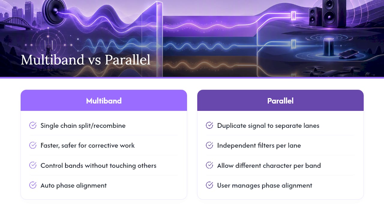
Multiband tools are faster and safer for corrective work, taming a boomy low end or controlling a harsh top end without touching the rest of the spectrum. Parallel lanes give you more control when you want each band to have a genuinely different character: heavy saturation on the low end, transparent compression on the mids, and a transient shaper isolated to the highs. The tradeoff is that parallel routing puts phase management entirely on you, since you're manually recombining signals that may no longer be time or phase aligned once you've added nonlinear processing to one lane and not another.
Crossover and filter selection
The crossover point and slope you pick determines how much the bands overlap, and that overlap is where most splitting artifacts live.
- Choose linear-phase filters when phase coherence matters more than latency. Linear-phase crossovers preserve the relative phase relationship between bands, which matters most when you're recombining several bands and want the sum to match the original signal closely. The cost is added latency, usually a few milliseconds, which can be a problem in live contexts but rarely matters in a mix session.
- Choose minimum-phase filters when latency matters more than perfect phase match. Minimum-phase crossovers introduce some phase shift near the crossover point but respond instantly, which is why they're the default in most hardware crossovers and live sound systems.
- Match the same crossover frequency and slope across every band boundary. A 24 dB/octave low crossover paired with a 12 dB/octave high crossover creates asymmetric overlap regions that are hard to predict by ear.
- Steeper slopes reduce overlap but increase phase rotation near the crossover point. A gentler slope, something like 6 or 12 dB/octave, overlaps more but usually sums back together more naturally.
Keeping phase and coherence intact
This is where most home studio splitting workflows fall apart, and it's rarely the filter choice that's the problem. It's what happens after the filtering, once you've added compression, saturation, or a delay-based effect to one band and not another.
Sum everything to mono regularly while you're building a multiband chain. If a band audibly thins out or a frequency disappears in mono, you've got a phase cancellation between lanes, usually because one band picked up latency the others didn't. A correlation meter helps here too. Readings drifting toward negative one on any given band boundary mean that band is fighting the others in the stereo field.
All-pass filters are the standard fix for phase misalignment introduced by nonlinear processing. They shift phase without touching amplitude, letting you nudge a lane back into alignment with its neighbors. Time alignment matters just as much: if a saturation plugin, tape emulation, or analog-modeled compressor adds even a sample or two of latency to one lane, that's enough to create a comb-filtering effect once the lanes sum back together.
Per-band processing choices
Each band earns different treatment once it's isolated, and the settings that work on a mix bus rarely transfer directly to a single split band.
- Compression on low bands usually wants a slower attack (10 to 30 ms) to let the initial transient through, with a medium release tied to the tempo, since over-compressing low end kills the punch that made the split worth doing in the first place.
- Saturation tends to work best on midrange bands, where harmonic content adds perceived loudness and warmth without muddying the low end or turning harsh in the highs.
- Transient shapers belong on whichever band carries the percussive information you're trying to control, often the low-mid crossover region for kick and bass separation, or the high band for cymbal and hi-hat definition.
Routing and verification
A typical parallel split routes the source to two or more aux or bus channels, applies a filter pair (high-pass on one, low-pass on the other, matched at the crossover point) on each, processes independently, then sums both buses into a master or subgroup fader. Keep unity gain in mind at each stage. Splitting a signal into three lanes and pushing each one hot before summing is a fast way to clip a bus you never intended to overload.
Verification isn't optional. A spectrum analyzer on the summed output should show a smooth transition through each crossover point, not a dip or a spike where the bands meet. A correlation meter confirms your stereo image survived the processing chain. And the listening check that catches what meters miss: solo each band alone, then solo the sum, then flip to mono. If something changes character between those three states beyond what you intended, back up and check your phase alignment before adding more processing.
Pro Tip: Build your multiband or parallel split with all processing bypassed first, and confirm the summed signal is phase-identical to the unsplit source before you touch a single compressor or saturator. That baseline check saves hours of chasing phantom phase issues introduced later in the chain.
What Causes Frequency Splitting in Resonant Systems?
Frequency splitting in coupled resonant systems, the kind found in inductive wireless power links, comes from a different mechanism entirely: coupling that's too strong, not filter design.
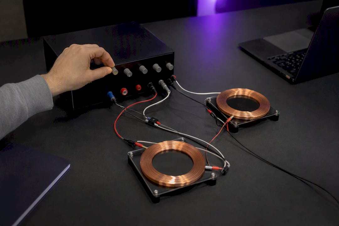
Every pair of resonant coils has a coupling coefficient, usually written as k, that describes how strongly energy transfers between them. There's a threshold called critical coupling, and as long as k stays below that threshold, the system behaves the way you'd want: a single, clean resonant peak at the design frequency, with efficiency rising as coupling increases. Push k past critical coupling, into what's called the overcoupled regime, and the single peak splits into two.
That splitting happens because the coupled system stops behaving like one resonator and starts behaving like two, through a process called mode hybridization. The PMC article on frequency splitting in inductive wireless powering describes this as the formation of even and odd resonant modes: one mode where the currents in both coils oscillate in phase, and another where they oscillate out of phase. Each mode has its own resonant frequency, and when coupling is strong enough, those two frequencies separate far enough to appear as two distinct peaks in the system's transfer function instead of one.
Here's what that looks like if you're taking measurements on a real system:
- Input impedance shows two local maxima instead of one as coupling increases past critical.
- Transfer efficiency at the original design frequency drops, even though total power transfer at the new split frequencies might be high.
- The transfer function (output over input, as a function of frequency) develops a visible dip right at the center frequency, flanked by two peaks.
- A basic two-coil circuit model, using coupled inductors with a mutual inductance term, predicts this behavior directly: solve for the resonant frequencies of the coupled system and you get two roots instead of one once k exceeds the critical value, matching what you'd plot as a double-humped frequency response curve.
A related but genuinely distinct phenomenon comes up if you ever encounter photovoltaic engineers or optics researchers using the term "spectral splitting." That's a different problem entirely, splitting broadband light into wavelength bands optimized for different solar cells, and it requires computationally designed diffractive optics, not simple filtering. One physics review demonstrated real efficiency gains from this kind of optical splitting, but the design process, iterative wavefront shaping rather than a crossover filter, has almost nothing in common with either audio band-splitting or WPT mode splitting. Worth knowing the distinction exists so you don't assume a technique from one domain transfers cleanly to another; a commentary on diffractive optics design challenges makes exactly this point, warning that spectral splitting gets conflated with basic filtering more often than it should.
Frequency splitting in resonant systems isn't automatically bad. Some multi-coil WPT topologies deliberately design around the split modes to widen the system's usable bandwidth. But in most single-frequency WPT applications, splitting means a real efficiency penalty at the frequency you built the system to run at, which is why suppression methods exist.
How Do You Suppress Frequency Splitting in Wireless Power Transfer?
The goal in most WPT designs isn't to eliminate coupling, it's to restore a single clean resonant peak at your design frequency without giving up the coupling strength you need for efficient transfer. Several suppression approaches accomplish that, each with different tradeoffs in complexity and hardware cost.
- Adjust the load resistance. This is the most accessible fix because it's purely electrical, no coil repositioning required. A study on frequency splitting suppression in four-coil WPT systems found that tuning the load resistor to an optimal value eliminated the split entirely and raised transfer efficiency at the original resonant frequency from 0.53 to 0.71 in tested conditions. That's a real, measured gain, not a theoretical projection, and it's achievable without touching coil geometry or spacing.
- Implement frequency tracking or adaptive tuning. Instead of fighting the split, some systems track whichever peak currently sits closest to the target frequency and adjust the driving frequency dynamically. This works well when coupling varies during operation, a phone moving on a charging pad, for instance, but it adds control-loop complexity and usually needs a feedback sensor and a tunable oscillator.
- Use non-identical resonant coils or intentional asymmetry. Making the transmitter and receiver coils slightly different in resonant frequency or Q factor can prevent the system from hitting the sharp overcoupled condition that causes splitting in symmetric designs, at the cost of a more complex design and tuning process.
- Adjust source or internal resistance. Rebalancing the effective resistance on the driving side changes the coupling behavior similarly to a load-side adjustment. The same IET research notes that electrical adjustments like this are generally more practical than mechanical ones, since physically repositioning coils to reduce coupling is often impossible once a device is packaged.
- Redesign relay coil or multi-coil network topology. In three-coil and four-coil systems, splitting can show up as different mode patterns, sometimes described as V-type, I-type, or W-type splitting, depending on the symmetry of the relay network. Adjusting how relay coils couple to the primary and secondary changes which mode pattern dominates.
A load-resistor fix is attractive precisely because it can be automated. Once you've characterized the relationship between coupling distance and optimal load, a control circuit can adjust load resistance electronically as coupling conditions change, without any moving parts or mechanical repositioning.
Verifying that a suppression method actually worked comes down to three measurements:
- A frequency sweep across the range where splitting was occurring, confirming a single peak has replaced the double peak.
- An impedance plot at the input, checking that the two local maxima seen in the overcoupled condition have merged back into one.
- An efficiency calculation at the design frequency, comparing power delivered to the load against power drawn from the source, before and after the suppression method is applied.
If you're running these tests on a bench setup rather than in simulation, keep the load resistor adjustment fine enough that you can map out the full curve of efficiency versus resistance rather than testing only two or three points. The optimal point is often narrower than engineers expect, and a coarse sweep can miss it entirely.
Worked Examples: Audio Splitting and WPT Suppression
Two reproducible walkthroughs, one for each audience, with concrete parameters you can test on your own material or bench setup.
Audio example: sub-bass splitting for a mix bus
- Split the source at 120 Hz using a matched high-pass and low-pass filter pair, minimum-phase if latency matters, linear-phase if you're not monitoring live.
- Route the low band through a compressor with a slow attack (around 20 ms) and a release tied to your track's tempo, then add gentle saturation to add harmonic weight without introducing distortion.
- Leave the high band mostly untouched, or apply light multiband compression if the upper-mid content is inconsistent in level.
- Sum both bands back to a bus fader, checking gain staging so the recombined signal doesn't clip.
- Measure the result: pull up a spectrum analyzer and confirm a smooth transition through 120 Hz with no dip or spike, then check a correlation meter for any negative drift at the crossover point.
- Do the mono check. Sum to mono and listen for thinning or cancellation in the low end specifically, since bass content is the most audible casualty of a bad phase relationship between split bands.
Expected result: a low end that feels tighter and more controlled without losing weight, and a high band that retains its detail because it wasn't run through the same compressor settings that would have squashed it.
WPT example: testing load-resistor suppression on a two-coil bench setup
- Set up transmitter and receiver coils at a fixed coupling distance known to produce overcoupling, confirmed by a frequency sweep showing two peaks instead of one.
- Measure baseline efficiency and impedance at the design frequency with a standard load resistor in place.
- Incrementally adjust the load resistance, sweeping across a range of values while re-measuring the frequency response after each change.
- Identify the resistance value where the two peaks merge into one, and record the transfer efficiency at that point.
- Compare against baseline. In published bench tests, this kind of adjustment took efficiency at the original resonant frequency from roughly 0.53 to 0.71 at the optimal load value, a meaningful gain achieved without moving the coils at all.
Pro Tip: Run the load-resistor sweep in both simulation and on the bench if you can. Simulated coupling coefficients rarely match a real bench setup exactly, since stray capacitance and imperfect coil alignment shift the effective coupling in ways that are hard to model precisely.
Troubleshooting checklist for both examples: if the audio split still sounds phasey after alignment, check for hidden latency introduced by any plugin in the chain, not just the obvious ones like compressors, since even a linear EQ can add a sample or two of delay. If the WPT suppression doesn't fully merge the peaks, verify your coupling coefficient calculation first. A miscalculated k value will send you hunting for the wrong load resistance entirely.
Why DSP architecture decisions shape frequency-splitting tools
Building a frequency-splitting plugin that behaves predictably under all these conditions comes down to architectural choices made well before a single filter coefficient gets written.
- Kai, whose signal-processing work informs Vector-dsp's plugin design philosophy, has focused on how multi-lane parallel architectures handle per-band processing without the phase penalties that plague naive implementations.
- Multi-lane parallel routing, where each frequency band gets an independent processing chain with matched latency compensation, avoids the comb-filtering problems described earlier in this article, but only if the architecture accounts for latency differences between lanes from the start rather than patching them in afterward.
- Every design decision here trades off against another: linear-phase filtering costs latency, more bands cost CPU, and tighter phase matching between lanes costs development complexity.
- Readers who want to see these tradeoffs implemented directly in a plugin environment rather than built manually with stock DAW tools can explore Vector DSP's plugin architecture for a look at how per-lane EQ targeting handles this in practice.
Why Most Frequency Splitting Advice Misses the Real Problem
The conventional advice on this topic tends to stop at the mechanics: here's how to set a crossover, here's the formula for critical coupling. What gets skipped is the fact that both audio splitting and WPT splitting fail for the same underlying reason: an unaccounted-for interaction between components that were treated as independent.
In audio, that's phase drift between bands after nonlinear processing gets added asymmetrically. In WPT, it's coupling strength that pushes past a threshold the original design didn't anticipate. Neither problem is really about the split itself, it's about what happens when the split parts get recombined or interact under conditions the initial calculation didn't cover.
If there's one thing worth prioritizing over everything else in this guide, it's verification. Measure before you trust a fix, whether that's a correlation meter in a DAW or an impedance sweep on a bench. The math and the plugin settings get you close. The measurement confirms whether you actually got there.
Get Precise Per-Band Control With Vector-dsp
Building the kind of multi-lane parallel splitting described throughout this guide usually means stacking multiple plugins and manually managing latency compensation between them, or living with the phase compromises that come from a single multiband tool. Vector-dsp's plugin architecture handles per-lane EQ targeting natively, so each band gets its own processing path without the manual latency matching that a stacked plugin chain forces on you.
That matters most for exactly the workflow covered above: splitting a signal into bands, processing each one with different compressors or saturation, and recombining without the phase cancellation that ruins a mono sum. The plugin lineup runs in VST3, AU, and AAX formats across the major DAWs on both Windows and macOS, with real-time low-latency processing built into the architecture rather than added on top of it.
If the phase-alignment and multiband workflows in this guide sound like problems you're currently solving with three or four separate plugins, check the Vector DSP product lineup for a demo download and see how a purpose-built multi-lane architecture handles it in one signal chain.
Sources
- Frequency Splitting Analysis and Compensation Method for Inductive Wireless Powering of Implantable Biosensors
- Increased Photovoltaic Power Output via Diffractive Spectrum Separation
- Frequency-division multiplexing